Isotropic Modeling of a Composite Panel of the Stern of a Fiberglass Boat Propelled by an Outboard Motor
Modelación isotrópica de los esfuerzos del espejo de un bote de fibra impulsado por motor fuera de borda
Patrick Townsend Valencia1
Abstract
We performed a theoretical and experimental study to define the best way to model the finite element sandwich structure aft of a fiberglass boat less than 15 meters in length, using an isotropic linear mathematical model that fits anisotropic material conditions. This is done by defining the properties of the ship’s fiberglass resin structure, which is representative of the influence of the forces acting during the glide on the geometry of the entire vessel. Formulation of the Finite Elements Method is presented, which works on the mathematical model to define the limitations of the results obtained. Isotropic material adjustment is calculated using Halpin-Tsai laws, developing its mathematical formulation for restrictions of modulus data entered as the finite element program experimentally calculated for each of the sandwich materials. The best-fit mathematical presentation to the modulus of the composite tool justifies the calculation thereof.
Key words: Sandwich, module, finite, composite resin
Resumen
Se presenta el estudio teórico para modelar en elementos finitos el sándwich del espejo de un bote de fibra menor a 15 metros de eslora, empleando un modelo matemático lineal isotrópico que se ajuste a las condiciones anisotrópicas del material. Esto se logra al definir las propiedades de la resina de fibra de vidrio empleada que sea representativo de la influencia de las fuerzas actuantes durante el planeo sobre la geometría de toda la embarcación. Se presenta la formulación del Método de Elementos Finitos sobre la cual trabaja el modelo matemático para definir las limitaciones de los resultados obtenidos. El ajuste isotrópico del material se calcula empleando las leyes de Halpin-Tsai, desarrollando su formulación matemática para conocer las restricciones del módulo de elasticidad que se ingresa como dato al programa de Elementos Finitos el cual es calculado de forma experimental para cada uno de los materiales del sándwich del espejo.
Palabras claves: sándwich, módulo, finitos, compuesto, resina
Date Received: September 25th, 2013 - Fecha de recepción: 25 de Septiembre de 2012 Date Accepted: February 20th, 2013 - Fecha de aceptación: 20 de Febrero de 2013
________________________
1NAVALOCEAN. President of Naval Oceanic Consultancy S.A. Guayaquil, Ecuador. e-mail: ptownsen@espol.edu.ec
............................................................................................................................................................
Introduction
Composite materials applied to structures of vessels have undergone notable technological development in recent years. Th eir application is common in sports, recreational, or boats for military use.
The favorable weight/structural resistance ratio makes composite materials an increasingly attractive alternative when requiring a low-weight hull able to withstand rigorous loads from the marine environment.
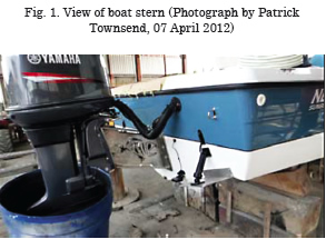
In numerous repairs to sports vessels less than 15m in length, I have noted that cracks appear in the outboard motor coupling zone. Th is zone is known as the stern; it withstands the thrust or the motor’s HP strength to make the vessel glide at the design speed and it corresponds to the transversal part or stern bulkhead or extreme of the vessel where the outboard motors of small gliding boats are installed.
The motors are placed on double steel plates on each side on the stern, for the pressure to distribute uniform stress on the composite material.
Assembly confi gurations exist, combining fi ber cloth with resin and marine plywood with which the composite panel or sandwich is put together, obtaining the necessary rigidity for the work expected.
Th e sum of all the hydrodynamic loads, the action of the wind over the bow, the vessel’s eff ective thrust through the action of the outboard motor, and other stress on the plate permit the vessel to glide at high speeds.
Regarding the material, the most-often used resin for this type of yacht construction is that of unsaturated polyester. When a catalyst is added to the resin, this combination creates a series of free radicals that cause the resin’s chemical elements to bond, forming an increasingly dense network that, in a fi rst phase, makes it turn to gel and, fi nally, harden into a vitreous state. With this, the composite material becomes a crosslinked, thermostable polymer, without rotation or movement of chains and which when solidifi ed acquires a fi rm rigidity that gives it structural characteristics
One of the most interesting mechanical properties of the unsaturated polyester resin is that of working under tension or compression only in the plastic or linear zone, going directly to the rupture or failure, without passing through the plastic zone.
This material is anisotropic and the model presented will fi t mathematically its properties to isotropic properties to obtain values of elasticity modulus equivalent to the composites.
The Finite Elements method is a powerful tool in the analysis of structures, and this work will develop the best-fi t model to study the appearance of cracks on sterns through motor action.
Materials and Methods
To calculate the loads acting on the boat at the moment of gliding when it develops its maximum power, it is necessary to defi ne the acting forces, corresponding to the air pressure on the boat, which is due to the speed, resistance of the vessel to advancing, which is a cause of the vessel’s velocity, V, and the hydrodynamic pressure. During gliding and thrust, which is the force exerted by the propeller, transmitted to the vessel’s hull through the propulsion system, in such a manner that the force acting on the ship’s stern is the sum of all forces, given their action-reaction condition.
Regarding the material, the most-often used resin for the construction of these types of yachts is unsaturated polyester. When a catalyst is added to the resin, this combination creates a series of free radicals that cause the resin’s chemical elements to bond, forming an increasingly dense network that, in a first phase, makes it turn to gel and, finally, harden into a vitreous state. With this, the composite material becomes a crosslinked, thermostable polymer, without rotation or movement of chains and which when solidified acquires a firm rigidity that gives it structural characteristics.
When using non-fiber nuclei, such as plywood materials, marine plywood, wood, cardboard, and others susceptible to making a structural contribution, such laminate is denominated sandwich.
Its anisotropy depends on that formed at the moment of manufacture. This means that in a sandwich panel used for yachts, its properties may depend on the orientation of the fibers and of the nuclei used with orientations only at 0 and 90°, depending on the assembly order assigning orthotropic properties to the material.
To learn how the vessel’s stern works against acting loads, the Finite Elements method (FEM) will be used to estimate the level of stress concentration upon the stern under acting loads. The use of the SAP2000 software, generally, has mathematical and structural limitations, which must be considered to have a good approximation of the results, given that the membrane and plate effects do not interact in a second order.
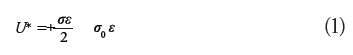
In its calculations, this program considers for a discretized surface, S, that the strain energy generated by the unit of volume, U*, is governed by the expression in terms of the unitary strain, σ, and the stress, ε.
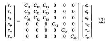
Given that the program will consider that the sandwich material is isotropic, that is, solid throughout its entire thickness, the ratio of the matrix of stress elements {σ} and of the unitary strain {ε} would be governed by equation 2.
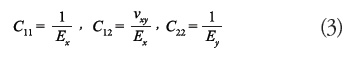
By definition, the elastic modulus will be the following in terms of the Cik coefficients indicated in expressions (3) and which correspond to the main directions of the elasticity modulus
By replacing equation 2 in 1, the strain energy in the volume, V, domain of finite elements, equation 4 is obtained.
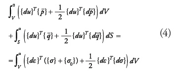
Upon solving, being the first-order analysis, dual differential products like ![]() are neglected so that equation 4 remains as:
are neglected so that equation 4 remains as:
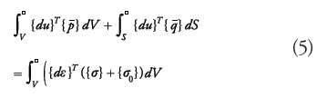
This equation is the principle of the virtual strains and assumes that stress remains constant during deformation. The Rayleigh-Ritz method solution is applied to this strain model by using the condition of the minimum total potential energy1.
Based on this, consider for the n layers of the laminate general expression (6), which relates the membrane stress (tensions), flexion (due to moments), and shear as σmem, σmto, ![]() respectively, which are obtained through integration, z, over thickness, t, at a distance, k, from the mean surface of each layer.
respectively, which are obtained through integration, z, over thickness, t, at a distance, k, from the mean surface of each layer.
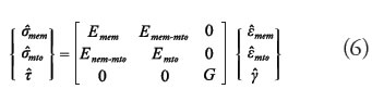
By solving, we obtain the ratios for the different stresses, which are expressed in equations 7, 8, and 9. 2:
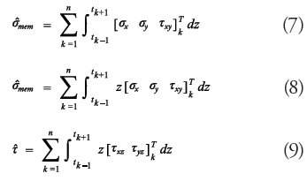
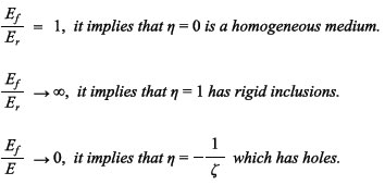
By relating the previous expressions to the Halpin- Tsai45 equation, which groups the modules in terms of ξ so that the behavior of the elasticity modulus of a composite material depends on the characteristics of form, packing regularity, load conditions, and aspect of the fibers, as noted in equation 10. The value of η depends on the Poisson constant and predicts the modulus according to the orientation of the fibers, f, and the volume of resin, r, defined by ϕf.
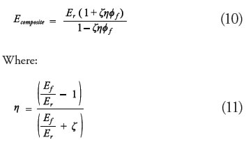
So that if:
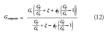
Rigidity is calculated in both directions with the generalized expression corresponding to the ratio between the elasticity modulus Poisson’s coefficient from which equation 12 is deducted, which fits that developed with Halpin-Tsai for rigidity.
This development permits fitting the sandwich’s material anisotropy to an isotropic plate material.
Given that the membrane strength, according to the equations to be used in the Finite Elements method is linear, that is, the membrane strength, Emem, of the elements does not produce flexion, Emto, and vice versa, so that the value of Enem-mto=0, leaves equation 13.
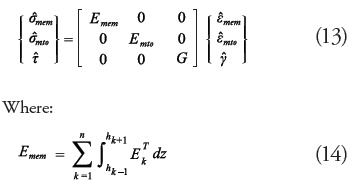
For the type of analysis, it may be concluded that Emem=Emto=ET, where ET is the total elasticity modulus of the sandwich. An approximate solution with series of equation 14 is that presented in equation 153.
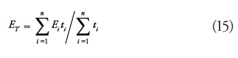
This permits calculating the linear elasticity modulus through the sum of all the sandwich modules, and apply it to the consistent fi nite elements model, given that the material’s anisotropic properties were fi tted to isotropic properties.
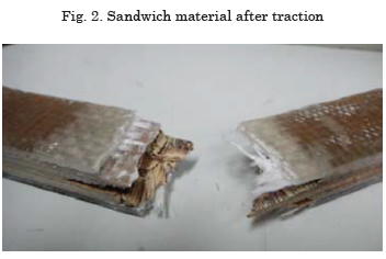
The value of the elasticity modulus is, thus, obtained with the uniaxial laboratory traction test, governed by the ASTM norm to standardize the dimensions of samples and test conditions like ambient temperature and rate of deformation (strain) applied by the team. Samples were brought to rupture, as noted in Fig. 2. Th e modulus will not have a constant value, given that the chains of the macromolecule reorganize due to the stress eff ect being that they are crosslinked polymers.
Results
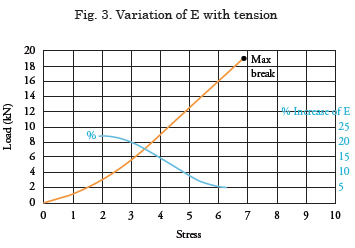
Elasticity modulus increases with traction because the chains of the macromolecule increase their resistance to it. Th is greater rigidity is propitiated by the growing presence of fi bers on the plastic layer, which restricts the reorganization of the macromolecules.
Fig. 3 represents the already discretized bow-stern Finite Elements model of a 15-m long speed boat made from the previously described materials. Th e conditions of symmetry and the necessary restrictions for a Finite Elements model have been applied, plus the values of the motor loads previously calculated on the stern. Also, note the model’s deformation profile.
The ends of the plate produce peaks on the stress, with the minimum bending stress being greater on the lower tip of the plate. If the installation of the plate exceeds the stress limit of the sandwich, the rupture should start at this lower point.
Fig. 4 analyzes the maximum bending stress on the model, having his level.
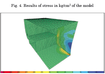
This can be explained by the model confi guration, given that the transversal bottom surface with its curvature, union with the keel and side reinforcement, tends to be more rigid and bend less. Th is is why it is noted in the fi gure that the other surfaces withstand less stress on the Shell elements through the action of the stern load upon them. Th is is the case of the deck, which has a given fl exibility because of its thickness and confi guration, which does not contribute significantly to the model’s rigidity, as achieved by the stern-bottom union.
We must highlight the existence of a stress peak toward the center of the model on the keel’s symmetrical attachment.
Conclusions
The results are reliable because the analysis prior to inputting the data onto the program, associated all the considerations of mathematical anisotropic approximations to isotropic material, permitting for the solution to be consistent.
Due to the numerical results, the failure produced in boats constructed must be related to the phenomenon of material fatigue. Because of the resin action, the sandwich is completely reconstituted in its length, as observed in the tests; this only gives way to cracks given that the material returns to its initial position without it continuing to crumble.
The effect indicated in g) is, then, a big advantage of using the fiber on other materials in naval construction for these types of vessels.
Because the stress level remains within the experimental linear range or elastic zone, the analysis with the SAP model yields a good representation of what actually happens in the boat, given that after applying the load the structure recovers to its original position.
References
A. MIRAVETE, “Materiales Compuestos I”. Editorial Reverté, Barcelona España, 2007.
A. HORTA, “Macromoléculas”. Librería UNED, Tercera Edición. 2002.
ASTM, “Standard Test Method for Tensile properties of polymer Matrix Composite Materials”. American Society for Testing and Material. USA, 2002.
B. MAC DONALD, “Practical Stress Analysis with Finite Elements”. Page 215. Dublin, Ireland. 2007.
C. MARISCAL, “Formulación y Evaluación de Proyectos”. Escuela Superior Politécnica del Litoral, ESPOL, 109 páginas. Guayaquil, Ecuador. 2001.
C. KASSAPOGLOU, “Desing and Analysis of Composite Structures”. First Edition, The Atrium & Southern Gate. London, UK. 2010.
D. CHUNG, “University Notes: Science and Applications: Composite Material”. Second Edition, British Library Cataloguing in Publication Data. State University of New York, Buffalo, USA. 2010.
D. FELDMAN, A. BARBALAT, “Synthetic polymers: technology, properties, applications”. London, United Kingdom.1996.
E. CAR, S. OLLER, E. OÑATE, “Tratamiento numérico de los materiales compuestos”. Centro Internacional de Métodos Numérico de Ingeniería. Madrid, España. 2000.
F. BILLMAYER, “Science of Polymers”. New York, USA 1975.
F. SINGER, A. PYTEL, “Resistencia de Materiales”. Impreso en México Tercera edición, 560 páginas. D.F. México. 1982.
G. GILI, “Arquitectura Naval: Teoría del buque y sus aplicaciones”. 574 páginas. España 1956.
___________________
1 Basic theory of the Finite Elements method presented by C. Zienkiewics in the text “The finite element method”, McGraw Hill company, Third Edition, Berkhsire, England, 2007. And by H. Lima in “Finite elements method Em Análise de estruturas”, Universidad de Sao Paulo, USP, Sao Paulo, Brasil. 2002.
2 Theory presented by E. Car, S. Oller, E. Oñate on page 47 of “Tratamiento numérico de los materiales compuestos”.
3 J Tegedor, in the text “Construcción de buques de pesca en poliéster reforzado con fibra de vidrio” from Librería Naútica, Madrid, 2001 presents this solution as a good mathematical approach by using “superposition of various layers”. Page 66.