Study of the weld ability of Aluminum Alloy 5083 H116 with
Pulsed Arc GMAW (GMAW-P)
Estudio de soldabilidad de aleación de aluminio 5083 H116 con arco pulsado GMAW (GMAW-P)
F. Cueca1
A. Patarroyo1
F. Rojas1
E. Solano1
A. Morales2
R. Muñoz3
Abstract
This research was based on the analysis of the weldability of aluminum joints, Alloy GL AW 5083 H116, with filler AWS 5.10 ER 5183 by GMAW-P process to determine the conditions of the heat-affected zone in the base material, depending on the heat input for the GMAW-P process with different pulsed technologies available in Colombia. The variables considered within this study were: welding positions (horizontal, vertical up, and overhead), type of welded joints (butt and fillet), and parameters for welding equipment (voltage, current, speed, power supply, speed development), and protective gas used (Argon, 100%). Non-destructive and destructive testing techniques were used to characterize the discontinuities found and the criteria to accept or reject the AWS D1.2 code (STRUCTURAL WELDING CODE - ALUMINUM by the AMERICAN WELDING SOCIETY). As a result, the investigation yielded the conditions for the application of filler material (ER 5183) on base material (alloy AW5083 GL H116), supported by Welding Procedure Specifications Documents (WPS) and Procedure Qualification Record (PQR) to implement in aluminum welding at the COTECMAR shipyard.
Key words: Welding, Pulsed arc. Pulsed MIG, HAZ, Discontinuities, Synergic Curves.
Resumen
Esta investigación se basó en el análisis de la soldabilidad de las uniones de aluminio, Aleación GL AW 5083 H116, con relleno AWS 5.10 ER 5183 mediante proceso de soldadura por arco metálico con gas (GMAW-P) para determinar las condiciones de la zona afectada por calor en el material base, dependiendo de la entrada de calor para el proceso GMAW-P con diferentes tecnologías de impulsos disponibles en Colombia. Las variables consideradas dentro de este estudio fueron: posiciones de soldadura (horizontal, vertical hacia arriba y por encima), tipos de uniones de soldadura (a tope y filete) y parámetros para equipo de soldadura (voltaje, corriente, velocidad, suministro de potencia, velocidad de desarrollo) y gas de protección utilizado (Argón, 100%). Se utilizaron técnicas de pruebas destructivos y no destructivas para caracterizar las discontinuidades halladas y los criterios para aceptar o rechazar el código AWS D1.2 (CÓDIGO DE SOLDADURA ESTRUCTURAL - ALUMINIO de la SOCIEDAD AMÉRICANA DE SOLDADURA). Como resultado, la investigación arrojó las condiciones para la aplicación del material de relleno (ER 5183) sobre material base (aleación AW5083 GL H116), apoyado por los documentos de Especificaciones de Procedimientos de Soldadura (WPS, por el término en inglés) y Registro de Calificación del Procedimiento (PQR, por el término en inglés) para implementar en soldadura en aluminio en el astillero de COTECMAR.
Palabras claves: Soldadura, arco pulsado. MIG pulsado, HAZ, Discontinuidades, Curvas Sinérgicas.
Date Received: October 22th, 2010 - Fecha de recepción: 22 de Octubre de 2010
Date Accepted: January 16th, 2012 - Fecha de aceptación: 16 de Enero de 2012
________________________
1Servicio Nacional de Aprendizaje SENA. e-mails: apatarroyo@misena.edu.co; elsomon7@misena.edu.co; facum64@hotmail.com;
hfrojas@misena.edu.co
2Corporación de Ciencia y Tecnología para el Desarrollo de la Industria Naval, Marítima y Fluvial COTECMAR. e-mail: amorales@cotecmar.com
3Universidad Nacional de Colombia, Faculty of Mechanical Engineering. Bogotá, Colombia. e-mail: rmuñoz@unal.edu.co
............................................................................................................................................................
Problem
The heat-affected zone (HAZ) is the section in the base material in which the mechanical properties are affected by the arc during the welding process in any metallic material. Depending on the amount of heat input, the magnitude of the HAZ increases or decreases as temperature on the material increases or decreases.
In aluminum alloys, the mechanical properties are seriously diminished by the effect of heat introduced by the welding process. It is more critical for the 5083 series alloys, which are heat-treatable alloys commonly used in the maritime industry and whose mechanical properties are assigned to their main alloying element, magnesium, and the residual stresses generated by a given hardening by cold work.
Documentation of the process of gas metal arc welding (GMAW) and pulsed-spray transfer is limited by these types of aluminum alloys in marine applications. The generation of pores and discontinuities can be attributed to the use of gas mixtures, lack of qualified technical welding personnel in this type of material, and nonupdating of standard skills for applications with GMAW and pulsed technology.
Introduction
Aluminum is a material with excellent mechanical properties and corrosion resistance; with its implementation in the shipbuilding industry, there is a decrease in fuel consumption and investment in vessel maintenance.
The GMAW process is a semi-automatic or automatic process, where an electric arc is maintained between a solid wire electrode that functions as continuous and the work piece. This process has different modes of mass transfer, short circuit, globular, and spray.
The shipbuilding industry is using Colombian high-strength materials like aluminum-magnesium alloys (GL AW Alloy 5083 H116) welded with filler 5183 AWSER 5.10 and shielding gas (100% argon (Ar)) that meet the requirements of tensile strength, as specified in codes.
State-of-the-art
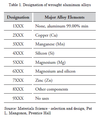
Designation of alloys
The designation of aluminum and its alloys are based on the quality of forged or cast products (molded). Table 1 shows the system for designating wrought alloys.
Characteristics of the forged alloy 5083 H116
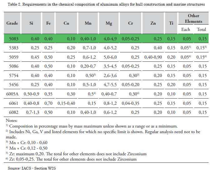
Chemical composition
The chemical composition of aluminum alloys must meet the requirements of the International Association of Classification Societies (IACS) Section W25 (Table 2).
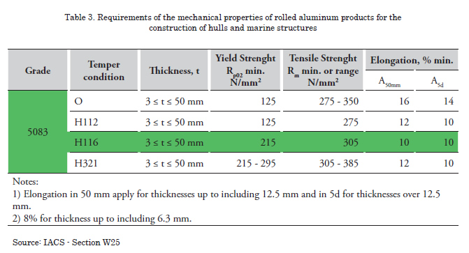
Mechanical properties
The mechanical properties must meet the requirements furnished in Table 3.
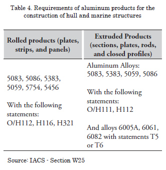
Requirements regarding materials and welds according to IACS - STANDARD W25
These requirements apply to aluminum alloys with thicknesses between 3 and 50 mm. The numerical designation (grade) of aluminum alloys and the description of basic statements are based on the designation of the Aluminum Association (AA), as shown in Table 4.
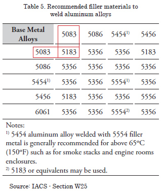
Recommended filler materials to weld aluminum alloys
Table 5 shows the input materials recommended by the American Bureau of Shipping (ABS) to weld aluminum alloys; remember that the solder joints in this investigation consist of 5083 H116 alloy plates 6.7 mm thick.
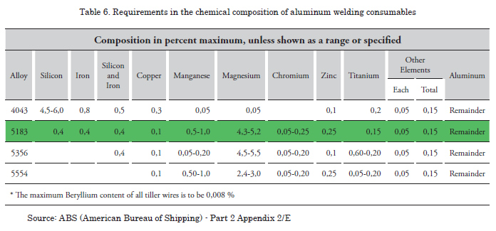
Required filler materials to weld aluminum alloy 5083 H116
The properties of consumables or filler material used to weld aluminum alloy 5083H116 comply with ABS code requirements and are characterized in the Metal Handbook, Volume 6, according to Table 6.
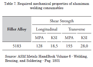
Required mechanical properties of aluminum welding consumables
The mechanical properties of aluminum welding consumables are shown in Table 7.
Requirements regarding materials and welds according to IACS - STANDARD W25
Within the development process used, different variables are presented below.
Essential variables of the process
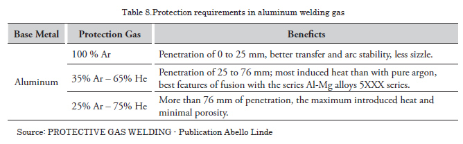
These are the numerical values of the parameters that directly affect the geometry of the weld deposit and its quality. Knowledge and control of these parameters is essential for quality welds because these variables are not independent given that a change in one of them produces or involves changes in some of the others. Key parameters to become part of the characteristics of welding and, therefore, the quality of the weld are: welding current, arc voltage, electrode free length (Stickout), polarity, forward speed, electrode diameter, electrode orientation and shielding gases, whose requirements are shown in Table 8.
Types of forces acting on the process
Surface tension
Gravitational force
Electromagnetic force
Transfer of metal
Short Circuit
Globular transfer
Spray
Pulsed Spray
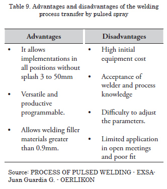
Advantages and disadvantages of the welding process transfer by pulsed Spray
Table 9 shows the advantages and disadvantages of the welding process of transfer by PULSED SPRAY.
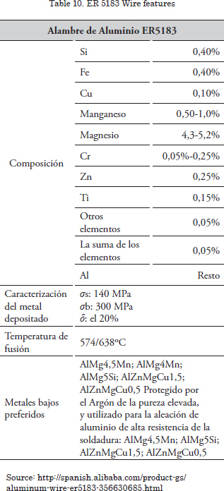
ER 5183 wire features
Welding ER 5183 are very good fluidity, low melting point (eutectoid point) and widely used in the shipbuilding industry.
Shielding gases (Argon, Ar, 100%)
In gas-shielded arc welding, the shielding gas can have a great influence on the properties of the weld metal. It is, therefore, necessary to check the solder in a controlled atmosphere. In welding with covered electrodes, the gases surrounding the arc come from the combustion of certain substances contained in the electrode coating. In the Metal Inner Gas process a protective atmosphere is achieved around the arc with a jet of gas, supplied through a nozzle, and from an external power source.
This gas has been used for many years as a means of protection in fusion welding. Argon is used in welding generally has a purity of 99.995%. When greater purity is required, the gas may be chemically purged at concentrations of 99.999%. One of the main qualities of argon is its low ionization potential. This means more stable arches, quiet, with few projections. It also reduces the arc voltage and, consequently, reduces the power of penetration. These properties make it highly recommended for small thickness welding. Pure Argon gas is rarely used as a safe protection in welding metals like aluminum, copper, nickel, and titanium.
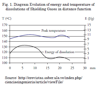
Aluminum welded joints have been extensively studied for years. Many researchers have focused on the metallurgical melt or weld phenomenon (Hermann et al., 1996; Hepples et al., 1992), others have characterized the mechanical properties (Debbouz and Navaï, 1997; Bloem et al., 2000) and, however, there are few studies on the evolution of the heat affected zone in these HAZ13 alloys. Fig. 1 shows the base-metal interface weld, increasing the energy of dissolution of the shielding gases, indicating a higher level of these changes on the aluminum matrix.
Experimental Design
The present study considered a type comparative experiment of setting up such parameters welding process used such as: gas type, number of joints, and number of specimens, joint design and base material.
Methodology
The methodology carried out during the investigation was as follows:
Search and selection of power supplies for welding with GMAW-P., obtaining samples for chemical and mechanical characterization of the base material, chemical and mechanical characterization of the base material , joint design according to the AWS D1.2 code , consolidation of boards and equipment as selected variables, development of the encoding matrix, assurance process traceability of materials, preparation and machined seals, welding joints, test-granting ticket, verification stamp discontinuities through visual inspection techniques and NDT Penetrating, determining the number of samples to obtain welded joints AWS D1.2 code, Court stamp, Specimen preparation and machining, Mechanical testing, collection and analysis of results.
Results
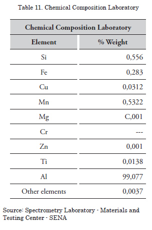
Spectrometric analysis performed on the base material in the laboratory results from the study genre similar to those referenced by the IACS-W25; Mg decreased and Cr content could not be recorded by the computer (Table 11).
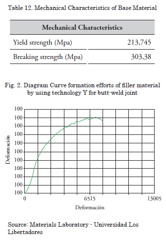
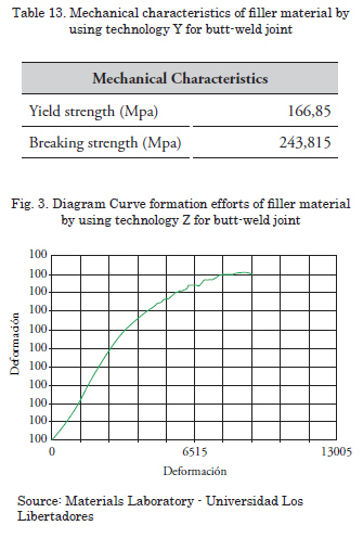
The results of the mechanical properties of the filler are shown in Tables 12 and 13 and in Figs. 2 and 3 for technology Y and Z, respectively; the values were greater than the efforts established by IACS-W25, registered in Table 7.
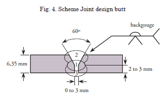
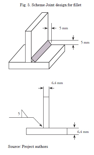
For the designs of butt joints and fillet is served in accordance with the parameters set in Figs. 4 and 5.
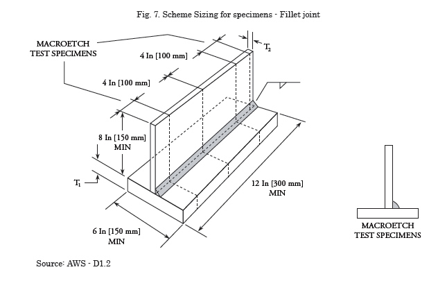
The acceptance and rejection criteria applied in Non Destructive Testing inspection techniques and visual inspection and penetrating liquid were according to AWS D1.2, which evaluated surface discontinuities, Figs. 6 and 7 show the designs of the stamps to obtain the specimens and subsequent machining and bending test for both butt joints, and fracture for fillet joints.

Macrography
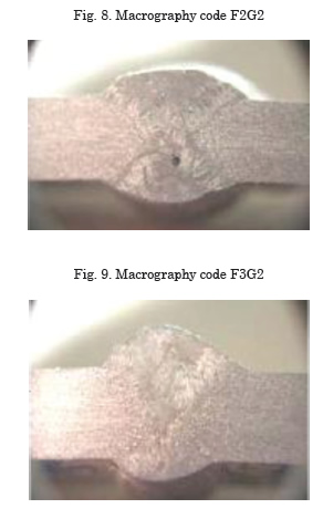
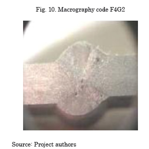
Figs. 8, 9 and 10 show macrographies with the observation points of the specimens obtained from the joint for Z technology, there is the base material, the heat affected zone (HAZ) and weld material; sections of macro-attack are also noted as indicated by the design.
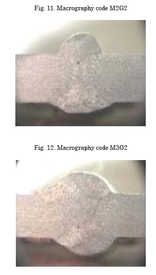
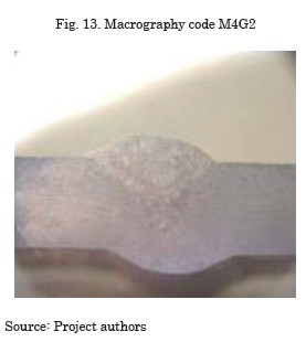
Figs. 11, 12, and 13 show macrographies correspond to the Y technology with the same features listed above.
It should be noted that for all the specimens macroattack solution was used 200cc HNO3 and 50cc HF at room temperature for 1 min to establish the dissolution of the precipitates and the recognition of discontinuities like rust, cracks, and inclusions.
Bending test
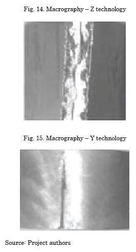
The bend test for butt joints was made after verification of these macroscopic conditions and showed a brittle fracture behavior of welded specimens in all the Z technology with almost complete breakdown, as shown in Fig. 14, while as for Y technology applications and the Fig. 15 shows the generation of transverse cracks through on the side of the root.
Fracture test
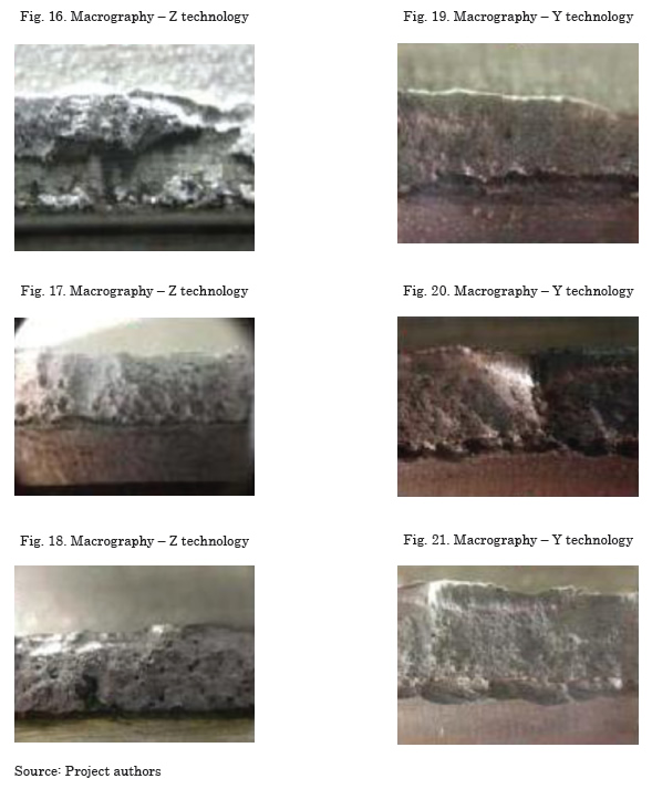
The fracture test was performed to fillet welded joints, whose behavior for the entire application with Z technology was the generation of pores and the lack of significant fusion, as seen in Figs. 16, 17 and 18. The Y technology shows in Figs. 19, 20 and 21 a better condition in the generation of pores and lack of fusion.
Metallographic tests
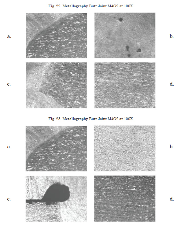
Fig. 22 shows microstructures with the results of metallographic test for the design of butt joints and Fig. 23 presents the results for fillet joints. Items designated as "a" and "c" in the design correspond to the HAZ, point "a" is evaluated at the top of this area and point "c" at the bottom. "b" is valued in the filler and point "d" in the base material.
Hardness tests
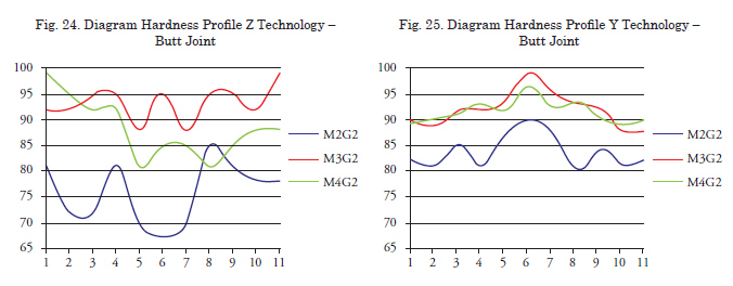
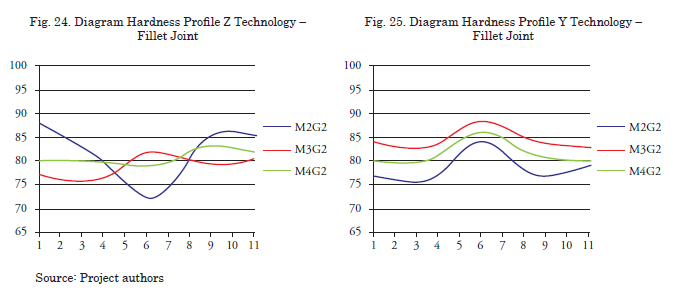
Fig.s 24 and 25 correspond to the hardness profiles for the designs of butt joints with Z and Y Technologies respectively, showing an asymmetry in the profiles for the Z Technology, while for the Y Technology and the tendency of these is to be symmetrical. The same behavior can be seen in Figs. 26 and 27 for the hardness profiles of the butt and fillet joints.
Conclusions
We selected two applications of GMAW-P technologies, which were designated as Y and Z, respectively, and these designs were applied to butt joints and fillet, with welding positions 2G, 3G, and 4G to stop and 2F, 3F, and 4F for fillet.
The preliminary characterization of the base material and filler with spectroscopy and mechanical tests allowed establishing comparisons with the theoretical references considered. The values of the mechanical tests for tensile test of butt joints show an increase of 28.1% in the yield stress and 24.5% for breaking strength on the welded joints with Z technology.
The visual analysis showed the weld areas of the base material, heat affected zone (HAZ) and weld material. The fracture testing of fillet joints shows better behavior mechanical with Z technology than the Y technology.
The metallographic analysis showed in more detail the microstructure of the zones of welded joints and discontinuities such as pores and confirms lack of fusion. This procedure was performed with a metallographic optical microscope connected to an image analyzer with a 100x magnification of gray levels because the interests of the investigation was to determine the overall condition of filler material in front of the base, in the micrographs is reached to appreciate dendritic areas (white points) in the HAZ with anisotropic orientations because of the possible phases present as Si, Mg 2 Si, and Fe3SiAl12 Fe2Si2Al9 within a matrix of aluminum-rich solid solution based on the results of chemical analysis.
A hardness profile in the symmetry of the points it has the Y technology, while technology Z shows irregularity in their profiles. The magnitude of higher hardness presents the welded joints with Y technology with nominations F3G2 with 95, HB and F3F2 with 82 in the filler, while for the appointments M3G2 and M3F2 were 99HB and 88 HB respectively.
References
Ingeniería de soldadura - Efraín Tabares A. - Profesor asociado a la Universidad Nacional de Colombia - Abril 5 del 2001 - Departamento de ingeniería mecánica - Universidad Nacional de Colombia.
Journal of Achievements in Materials and Manufacturing Engineering - Arc voltage behavior of one drop per pulse mode in GMAW-P - VOLUME 17- ISSUE 1-2 -July- August - 2006.
SUNARC - Tecnología en soldadura- www.sunarc. com
GASES DE PROTECCIÓN PARA LA SOLDADURA - Publicación Abello Linde.
PROCESOS DE SOLDADURA POR ARCO PULSADO - EXSA- Juan Guardia G. - OERLIKON.
MANUAL DEL SOLDADOR - Germán Hernández Riesco - Asociación española de soldadura y Tecnología de unión.
EL LIBRO DEL ALUMINIO, INDUSTRIA Y ARQUITECTURA - Alu-stock S.A.- capitulo 10 - información técnica.
MANUAL DE SOLDADURA MODERNA - Tomo 1 - segunda edición - Howard B. Cary - Prentice Hall Hispanoamericana S.A.
AMERICAN BUREAU OF SHIPPING - Requirements for Materials and Welding - PART 2 - Aluminum.
HUEHL, ROBERT O. Diseño de experimentos 2ª edición Thomson Learning.
AWS D1.2 - Structural Welding Code - Aluminum