Stephen J. Kennedy 1
Aldo E. Martino 2
Alireza Mirzaei 3
Fabio Zapata 4
1 Intelligent Engineering Ltd. Ontario, Canada. Email: sjk@ie-sps.com
2 Intelligent Engineering Ltd. Ontario, Canada. Email: martino@ie-sps.com
3 Intelligent Engineering Ltd. Ontario, Canada. Email: mirzaei@ie-sps.com
4 KHALELA S.A.S. Cartagena, Colombia. Email: proyectos@khalela.com
Date Received: February 24th 2017 - Fecha de recepción: Febrero 24 de 2017
Date Accepted: March 14th 2017 - Fecha de aceptación: Marzo 14 de 2017
MARPOL regulations stipulate that all single hull oil carrying barges must be made of double skin construction or modified by an alternate construction provided that the construction ensures at least the same level of protection against oil pollution. It is be demonstrated that the proposed alternative method of design, made with a SPS Compact Double Hull (CDH) applied to the bottom hull, does not rupture under the prescribed grounding event (no rupture, no oil outflow, no oil pollution).
A sophisticated finite element model was developed to simulate the grounding event for a single hull barge. Based on the experience gained from this simulation, a comparative grounding simulation study was conducted where a specified embedded object causes rupture of the outer and inner hull for double hull construction (a non-zero probability of oil outflow and pollution) and no rupture of the SPS CDH which demonstrates superior performance.
Key words: Equivalent or superior performance, impact resistant hull structure, robust bow construction, Sandwich Plate System (SPS), Compact Double Hull (CDH).
Las regulaciones de MARPOL estipulan que las barcazas de casco sencillo deben ser hechas a partir de una construcción doble casco o modificadas por un método alternativo que asegure al menos el mismo nivel de protección contra los derrames de petróleo. Se ha demostrado que el método de diseño alternativo propuesto, hecho con un doble casco compacto (CDH) de SPS (Sandwich Plate System) aplicado en el fondo de la embarcación no sufre ruptura sobre eventos encalle (no hay ruptura, no hay flujo de petróleo, no hay contaminación por petróleo). Un modelo de elementos finitos sofisticado fue desarrollado para simular un evento donde una barcaza de casco sencillo encalla. Basada en la experiencia obtenida de esta simulación, un estudio de simulación comparativo fue desarrollado donde un objeto embebido causa la ruptura de la parte exterior e interior de un casco con construcción de doble casco (una probabilidad distinta a cero de flujo de combustible y contaminación) y la no ruptura del doble casco compacto con SPS mostrando un mejor desempeño.
Palabras claves: Rendimiento equivalente o superior, estructura de casco resistente a impactos, construcción de arco robusta, sistema de placa sándwich (SPS), doble casco compacto (CDH).
The ABS Rules for Building and Classing Steel Vessels for Service on Rivers & Intracoastal Waterways[1] (ABS, 2016) stipulate a double hull dimension of 610 mm (2 ft) for protection against oil pollution in the event of a collision or grounding event and a minimum clearance of 460 mm (18 in.) for passage between framing throughout the double sides and double bottom. These requirements are specified by the Code of Federal Regulations (CFR), Title 33, Chapter I, Subchapter O, Part 157 Subpart B, Section 157.10d(d). The structure that satisfies the current regulations is a double hull barge with double sided and double bottom construction designed in accordance with Resolution MEPC.110 (49) “Revised Interim Guidelines for the Approval of Alternative Methods of Design and Construction of Oil Tankers under Regulation 13F(5) of Annex I of MARPOL 73/78”[4] (International Maritime Organization, 2003). The double hull barge construction inherently has oil outflow characteristics for a certain grounding event that are in accordance with MEPC.110 (49)[4].
MARPOL regulations[3] (International Maritime Organization, 1973) stipulate that all single hull oil carrying barges must be made of double skin construction or modified by an alternate construction provided that the construction ensures at least the same level of protection against oil pollution. It can be demonstrated by calculation, using appropriate calculating procedures, that the proposed alternative method of design, made with a SPS Compact Double Hull (CDH) applied to the bottom hull does not rupture under the prescribed grounding event (no rupture, no oil outflow, no oil pollution).
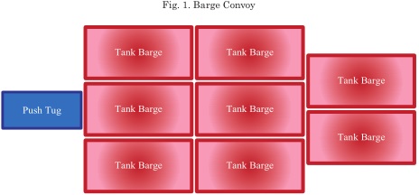
The barge convoy used for this study typically operates in a variety of different configurations, where one such configuration is illustrated in Fig. 1 consisting of 8 barges and a push tug with a total mass of 10,514 tonnes and a maximum velocity of 16 km/hr (4.44 m/s). The kinetic energy is equal to 104 MJ. For navigational channels that are dredged regularly, the conditions of the river bed (soil type and maximum rock size) are well known. It is assumed that the river bed is mostly sand with some small areas of rocks with a maximum diameter of 100 mm which are washed downstream.
A grounding simulation for a single hull barge structure was initially undertaken to demonstrate that the modeling assumptions are appropriate and that the simulation is a reasonable representation of the actual conditions. Based on the results from this simulation, a comparative grounding simulation study for the double hull construction and SPS CDH construction was completed[2] (Intelligent Engineering, 2016). The performance evaluation of the two barge conversion options including an introduction of the two structural configurations, design criteria, details of the finite element model and interpretation of the simulation results are presented.
Part 3, Chapter 2, Section 1, Clause 5.5 of the ABS Rules for Building and Classing Steel Vessels for Service on Rivers & Intracoastal Waterways[1] stipulates a double hull dimension of 610 mm for protection against oil pollution in the event of a collision or grounding event. This rule is dictated by the requirement to provide access to complete welding operations during the construction of the double bottom. The structure that satisfies the current regulations is a double hull barge with double sided and double bottom construction designed in accordance with Resolution MEPC.110 (49)[4]. The double hull barge construction inherently has oil outflow characteristics for a certain grounding event that are in accordance with MEPC.110 (49)[4].
Resolution MEPC.110 (49)[4] employs a probabilistic methodology to determine the pollution prevention index to evaluate equivalency of a design concept to a double-hull design and recognizes that oil outflow will occur with some probability. It can be demonstrated by calculation, using appropriate calculating procedures, that the proposed alternative method of design, made with a SPS CDH applied to the bottom hull, does not rupture under the prescribed grounding event (no rupture, no oil outflow, no oil pollution). The alternative would then be equivalent or better than the double-hull design which ruptures for the same grounding event (a on-zero probability of oil outflow and pollution). ABAQUS 2016 (Simulia, 2016)[6] will be used to conduct the grounding event simulation calculations in accordance with Clause 6.2.1 of Resolution MEPC.110 (49)[4].
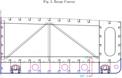
The double hull construction is typically applied along the cargo tank region and tapered over a small localized area of the bow region. Fig. 2 illustrates a typical mid-ship section of a conventional double hull design. A typical method for the conversion of a single hull construction to double hull construction involves welding the outer hull and additional internal structure to the existing inner hull. The space between the inner and outer hull is 610 mm making it problematic to complete weld operations and conduct inspections. Furthermore, conversion using the aforementioned method has the following disadvantages: additional complex structure with new confined spaces; increased material and labour costs associated with processes such as surface preparation, shop priming and coating; increase in construction schedule, reduction in cargo capacity and; increased inspection and maintenance requirements.
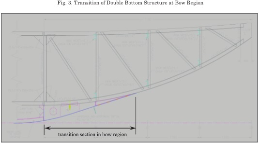
The ABS Rules which stipulate that single hull barges are to be converted to double hull construction only apply to the cargo tank region. The transition section for the double bottom construction which occurs from the cargo tank region into the bow section, as illustrated in Fig. 3, are not given any special consideration within the rules. The nature of the grounding event is such that initial impact occurs at the bow and causes damage along the length of barge continuing through to the first transverse bulkhead where rupture may occur in the outer hull or both the outer and inner hull. This type of event is not a collision event as the barge should ride over top of the embedded objects. The most important section of the vessel with respect to grounding events is the bow region which for conventional double hull conversions can only be made solid from the outside and are welded to the framing structure on the inside as accessibility is difficult which can result in poor workmanship, poor welding quality and lead to corrosion issues. The numerous intersecting steel pieces make it more prone to crack propagation, fracture and rupture at locations of stress concentrations. These issues and concerns associated with double hull construction are addressed with the proposed SPS CDH design which is described in the following section.
SPS CDH construction provides risk reduction benefits over that of double hull construction including: a significant increase in impact resistance, a strengthened bottom structure that reduces critical stresses, schedule reduction for fabrication and installation, reduced risks during fabrication, less maintenance, and elimination of risks and costs for through life void space inspections.
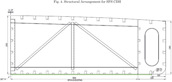
For the SPS CDH construction, as illustrated in Figure 4, the issues described in the previous section for the double hull construction are advantageously eliminated and/or addressed. The SPS CDH design eliminates problems associated with welding and accessibility as all construction is from the outside. The bow section, cargo tank regions and areas beyond the cargo tanks on the aft end are armoured with a SPS Overlay across the full width from halfway within the double sides (as illustrated in Fig. 4 and drawings in Appendix A) which offers greater impact resistance for a specified grounding event. The armoured bow section, which consists of a thicker SPS Overlay (12 mm thick faceplate and 20 mm thick polyurethane core), properly recognizes the type of event as the greatest protection is placed where the initial impact is anticipated. By increasing the amount of steel area associated with plastic deformation for areas beyond the first transverse bulkhead, rupture is prevented where the energy from the initial hit is absorbed. Full length protection is required as the barge convoy has sufficient mass, velocity and kinetic energy (104 MJ) that it will run completely over top of the embedded object without stopping.
SPS CDH construction will provide the required protection where rupture is prevented for a specified grounding event. No rupture, no oil outflow, no oil pollution. If the outer hull of the comparative double hull bottom structure ruptures for the same grounding event, then there is a nonzero probability that cracks about the rupture for this high energy event will propagate through the webs of interconnecting steel into the inner hull leading to oil outflow. The rupture of both the outer hull and inner hull would directly lead to oil outflow. The SPS CDH construction must then be considered to be equivalent to or better than a double bottom hull for protection against oil outflow and oil pollution.
A grounding simulation for a single hull barge structure was conducted using ABAQUS to: ensure the simulation of a grounding event is a reasonable representation of the actual conditions; verify that the soil characteristics and behaviour are accurately modeled and; evaluate the effect of different embedded object shapes.
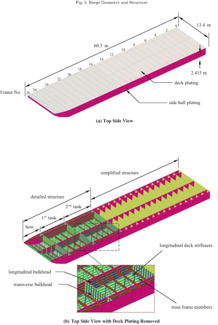
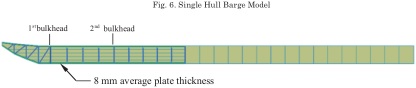
IE has constructed a finite element model representation of the barge convoy using SolidWorks 2016 as illustrated in Fig. 5. The barge convoy consists of 8 barges and a push tug with a total mass of 10,514 tonnes and travels with a maximum velocity of 16 km/hr (4.44 m/s) which gives a kinetic energy equal to 104 MJ. The detailed structure of the model includes the bow, 1st tank and 2nd tank, as illustrated in Fig. 5b, which represents a single barge. The simplified structure of the model represents the remaining parts of the barge convoy (7 adjoining barges and push tug) which are modeled as added mass (including oil in tanks). The simplification of the structure beyond the 2nd tank and the use of shell elements improve the computational efficiency of the analyses. The bottom plating of the single hull construction consists of a single layer of stiffened steel plate schematically illustrated in Fig. 6. An average thickness of 8 mm was used for the bottom plating and was determined from ultrasonic thickness measurements.
A series of full explicit dynamic analyses with appropriate material properties and dynamic parameters have been conducted (SolidWorks geometry model exported into ABAQUS 2016) to investigate the effect of different embedded object size, shape and configurations on the damage caused from a grounding event. The embedded object can either be classified as a rock or a manmade object of an unknown description (ex. spud). The mass of the barge convoy is a million times greater than the mass of a prescribed 100 mm spherical rock which is ~10 kg. The barge convoy simply pushes these small rocks into the sandy soil with no damage to the original barge structure. Obviously, the amount of damage will increase with an increase in rock size. The shape of the rock and its orientation with sharp edges could cause local rupture of hull plating. Regardless of the embedded object size, shape or orientation, the kinetic energy is so large that the barge convoy will pass over the object causing damage along the full length of the barge. The magnitude and extent of the damage is directly related to the embedded object geometry, the resistance of the soil provided to the object as it is embedded into the soil mass and to the vertical force exerted on the object as the barge convoy bounces along over top. The vertical force exerted downward (gravity) when the barge is deflected upwards by the embedded objects that it rides over top of is described in more detail in Section 3.3. Th is will vary depending upon the extent to which the barge convoy is displaced out of the water relative to the draft position. To simplify the analyses this is assumed to be a constant.
The soil characteristics and properties selected for the grounding simulation was based on a loose sandy layer. The exact material properties for the sand were not available hence the material properties were selected based on two references. The density, modulus of elasticity and Poisson's ratio of the soil were chosen based on Subramanian (2016)[7]. The plasticity material input data, which includes the friction angle, latency angle and cohesion, were selected based on a research paper by Pichler (2012) [5]. Table 1 below gives the material properties and plastic material input data used for modeling the soil for the grounding simulation.
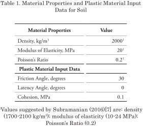
To determine a suitable cohesion value, a model of the embedded object penetrating into the soil was built and a cohesion value was calibrated based on the model. The cohesion value was determined to be 0.05 however ABAQUS automatically adjusts this value to 0.1 which is the minimum cohesion value used for the grounding simulations.
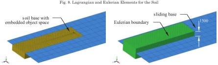
Fig. 7 illustrates the sandy soil and the sliding base on which the barge sits. The sliding base was fully restrained in all degrees of freedom to simulate the buoyant force. The soil beneath the barge was modeled using Coupled Eulerian Lagrange (CEL) elements to avoid excessive distortion. The degree of freedom normal to the surfaces of the ground was restrained to prevent soil outflow. The embedded object was positioned right between two longitudinal stiffeners in front of the barge and half buried in the ground. The contact between the barge and sliding base is frictionless, while the friction coefficient for all the other parts was assumed to be 0.3. The sandy soil measures 4 m in depth and 6 m in width for the single hull barge and SPS CDH models and 9.5 m in width for the double hull barge model. For the double hull model, the soil behaviour (movement) was influenced by the accumulation of soil mass in front of the barge and subsequent lateral displacement of the soil which extended beyond the specified CEL boundary. The width of the CEL boundary was increased for the double hull model to ensure that the soil is capable of displacing laterally without accumulation (build-up) of soil near the longitudinal CEL boundary.
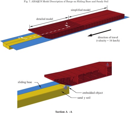
Fig. 8 illustrates the Eulerian and Lagrangian components of the soil base. The actual soil including the embedment depth of the embedded object was created using a Lagrangian mesh. The Eularian mesh was created to specify the boundaries within which the soil can flow. A soil depth of 1.5 m over the sliding base elevation was selected to allow soil flow in the vertical direction.
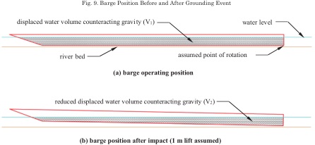
The buoyancy uplift force is equal to the volume of water displaced by the barge, counteracting the weight of the barge plus the vertical load (oil barrels). As the barge hits the embedded object, it is assumed that that the extreme position occurs when the front is lifted 1 m as illustrated in Figure 9b. For a 1 m width of the barge, the change in area of water can be used to estimate the gravity force on the barge after impact. Based on the geometry of the barge as shown in Fig. 9, V1 and V2 are approximately 102 m3 and 72 m3 respectively which give a reduction in the buoyancy force of approximately 30%. For this reason, it is assumed that the vertical gravity force acting on the barge is 0.3g during the entire analysis. This may not be the case under real operating conditions because the gravity reaches this magnitude only when the tip is raised 1 m, and will be less than this amount when the barge is fully horizontal. It is conservatively assumed that the gravity force of 0.3g is acting on the barge in the vertical direction during the entire simulation.
In the analyses, different types of grounding objects with various dimensions and shapes were modeled such as a spherical, rectangular block shape and a prism-block shape object. All objects were partially buried with varying depths and orientations. The effect of the embedded object shape on the damage underneath the barge was unknown, therefore for simplicity a spherical object with a diameter of 100 mm was selected as the first object. The rock was buried 50 mm in the sand. The magnitude of kinetic energy of the barge (104 MJ) caused the rock to be rolled and immediately pushed into the sand. To permit more damage accumulation to the barge, rocks with larger diameters (250 mm, 500 mm, 1000 mm, and 1200 mm) were examined. It was found that larger rocks, typically larger than 500 mm in diameter were capable of substantially damaging the bottom of the barge along the length. Larger spherical objects started to roll with the barge and move along its direction due to contact and friction, especially when the object hit hard spots such as the end of the bow. The object also penetrated in the sand as the barge moved over them, causing yielding underneath the barge and in some cases rupture.
Considering that the mechanism of grounding events is extremely complex in reality, finite element analysis is not capable of simulating all the aspects of the events. To simplify the problem and simulate the grounding events more efficiently and accurately, a list of assumptions were made and are given below:
A nonlinear explicit dynamic analysis was performed using non-linear material behaviour for the model with the exception of the embedded object where a high elastic modulus, equivalent to steel, representing a rigid object was used. The material properties and damage criteria defined for each component of the barge model are summarized in Table 2.
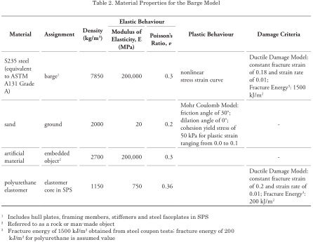
The ductile damage initiation criterion for metals in ABAQUS was used for the fracture simulation. The post-damage behaviour which controls stiffness degradation of the material was included in the simulation by using the damage evolution feature of ABAQUS. As the damage criteria is satisfied, stiffness degradation is applied to the material and the element starts losing its stiffness until a point where the plastic strain in the entire element reaches the specified fracture strain. The element will be removed if the plastic strain at all integration points in the element exceeds the fracture strain.
For the grounding event simulation of the single hull barge, the embedded object used was spherical and the initial size set equal to the maximum rock dimension (100 mm diameter) as determined from dredging operations. The mass of this rock is ~10 kg, as compared to the barge convoy with a mass of 10,514 tonnes, and has no effect on the movement of the barge and no energy absorbed as the rock is simply pushed into the soil. The dimensional size of the rock was increased proportionately by its diameter to 5x, 10x and 12x which is equivalent to an increase in mass by 125x, 1000x and 1728x for rock diameters of 500 mm, 1000 mm and 1200 mm respectively.
The damage accumulation on the outer hull plate of the single hull barge from a grounding event simulation with 100 mm and 250 mm diameter rocks demonstrates that there is no effect on the outer hull structure as the object was simply pushed into the soil. For the 500 mm, 1000 mm and 1200 mm diameter rocks, the small amounts of energy absorbed were determined to be 6 MJ, 16 MJ and 17 MJ respectively. The change in energy absorbed is of no consequence for larger rocks of increasing mass and is only dependent upon the shape and embedment of the rock in the soil. The larger embedded objects are at the extreme range of rock sizes and are unlikely to be found in the navigational channel as dredging operations would result in the removal of rocks of this size.
Assuming a standard deviation (o) of 100 mm for the mean rock size of 100 mm, the probability of occurrence for large embedded rocks within the channel with a minimum diameter of 500 mm (5o from the mean) is 0.00003%. The larger rocks cause some damage and rupture of the outer hull plating with reliance on crack propagation for continued damage as the barge moves along over top of the rock. The Navigation and Vessel Inspection Circular (NVIC) No. 15-91[8] (United States Coast Guard, 1994) provides a methodology for calculating the critical crack length which was estimated to be 15 inches. The critical crack length, which may lead to crack propagation and rupture of the hull structure, is debatable.
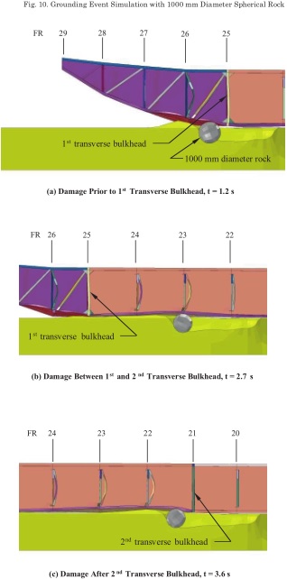
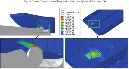
The grounding event simulation for the single hull barge in contact with a 1000 mm diameter spherical object is shown in Fig. 10 where damage prior to the 1st bulkhead, damage between the 1st and 2nd bulkhead and damage after the 2nd bulkhead are illustrated in Fig. 10(a), (b) and (c) respectively. Most of the damage occurs over the first 0.6 seconds as illustrated by the plastic deformation (Fig. 11) with subsequent rupture occurring when the rock was beyond the first bulkhead. After rupture of the outer bottom plate, there is continuing plastification (small amount of energy absorbed) and damage to the outer bottom plate along the length. The model correctly represents the embedded object to soil interaction and the interaction between the barge, the embedded object and the soil. The most damage occurs upon initial contact with the bow, the most critical section, and the amount of damage may or may not exist based on the assumptions made (rock is not deformable; rock is more dense than assumed). Comparison of the damage accumulation to the barge from the 1000 mm to the 1200 mm diameter rock showed no real difference as rupture of the outer bottom plating also occurred in the vicinity of the transverse bulkhead and plastification continued over the length of the barge.
The simulation demonstrates that the modeling assumptions are working correctly and that a deterministic definition of the rock size is appropriate where the embedded grounding object is selected based upon its interaction with the barge where rupture is caused to the double hull construction and no rupture to the SPS CDH.
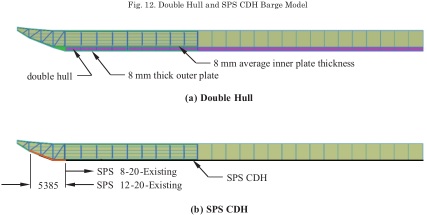
Two barge configurations were modeled which include double hull construction and SPS CDH where both are based on the single hull construction. The double hull construction is based on an outer bottom plating thickness of 8 mm and internal framing structure that is added to the single hull construction. The double bottom construction is applied up to but not including the bow section, where a tapered transition is made from the cargo tank boundary to the initial section of the bow as schematically illustrated in Fig. 12a. The SPS CDH consists of the single hull construction with an SPS Overlay applied beneath the barge where a SPS 8 20 Existing (8 mm thick steel faceplate for outer bottom plating and 20 mm thick polyurethane elastomer core) is applied over the main body and a SPS 12 20 Existing is applied over a section of the bow region as schematically illustrated in Fig.12b. The grounding simulation study for the single hull barge identified that a localized area of robust construction in the bow region is required where initial contact with the embedded object is anticipated. The energy absorbed upon initial contact will be minimal as the robust construction in the bow region will allow the barge to deflect upwards and ride over top of the embedded object. Recognizing that the energy absorption will be minimal, the SPS CDH design with two different faceplate thicknesses has been tailored to mitigate the damage to the outer hull structure from a grounding event. Corresponding drawings for the SPS CDH are provided in Appendix A. Embedded Grounding Object
The shape, amount of embedment, and orientation of the embedded grounding object was selected based upon its interaction with the barge where rupture was caused to the double hull construction but not to the SPS CDH. The prism-block shaped object illustrated in Fig. 13 was arrived at empirically, was easily modeled with artificial properties, contains angular profiles, and has an embedment depth that was easily modified. The mass of the embedded grounding object, which is more than 2 times larger than the largest rock tested in the grounding simulation for the single hull barge, was oriented to cause the maximum resistance with the soil such that the rolling resistance of the embedded grounding object is increased allowing the barge to ride over top. The embedment depth of the embedded grounding object used for the grounding simulations is 800 mm.
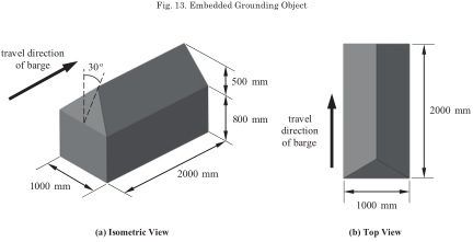
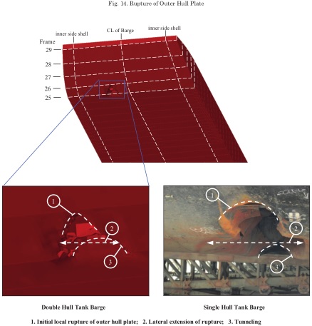
Fig.14 illustrates the rupture of the outer hull plate in a single hull barge and similar damage from a corresponding grounding simulation model of a single hull barge. The damage to the outer hull plate is consistent with damage associated with other man-made embedded objects such as a spud where local rupture of the single hull is highly localized in the vicinity of the embedded object. The lateral extension as the object passes over the 1st transverse bulkhead and tunneling are again localized and associated with contact with the embedded object as it is driven into the soil. A detailed description of the grounding simulation results for the double hull construction and the SPS CDH is presented in the following section.
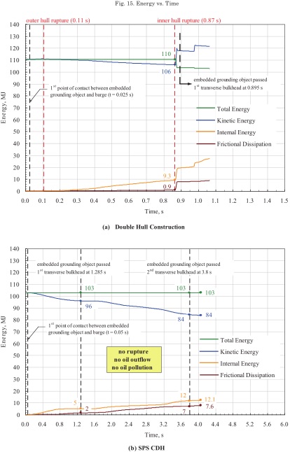
For the grounding event simulation of the double hull construction and SPS CDH, the performance is summarized in the energy curves illustrated in Fig. 15. As shown in the graphical energy plots, the rupture of the outer hull for the double hull occurs very quickly upon contact with the embedded object (0.11 seconds) which manifests itself into the rupture of the inner hull when the embedded object crosses the first transverse bulkhead (0.87 seconds). Subsequently, the energy curves have less meaning as the elements are highly distorted and become disassociated with the existing barge body. The corresponding graphical energy plot for the SPS CDH illustrates that the initial contact is absorbed and the barge rides over top of the embedded object with no rupture, no oil outflow and no oil pollution. The total energy absorbed is relatively small even for an object with more than twice the mass but similar resistance and with similar energy absorbed as for the spherical embedded object with a 1200 mm diameter. The energy absorbed during the grounding event is not the key design driver, but simply the amount of damage.
The grounding simulation results are best described through a series of illustrations which show the embedded object with respect to the barge and the plastic strain as a function of time. The corresponding images are given in Fig. 16 and Fig.17 for the double hull construction and SPS CDH respectively. For the double hull construction, rupture of the outer hull occurs at the point of contact while the inner hull ruptures as the embedded object passes the first transverse bulkhead. Interaction of the embedded object and the soil causes the outer hull plate to rupture over a single frame plus half of a frame on each side. The damage grows throughout the time history, including damage to the internal frame structure. The rupture of the hull plating increases the possibility of propagating cracks associated with this type of ground event (speed, large mass and little or no reduction in energy) and would lead to oil outflow and oil pollution. The largest extent of damage was identified at the end of the bow and at the transverse bulkheads which are hard spots. Initial rupture and damage may occur sooner and be more severe than predicted by the grounding simulation model as the thin tapered section at the end of the bow constructed with slotted welds are not ideally connected to the inner bottom as in the model.
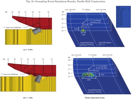
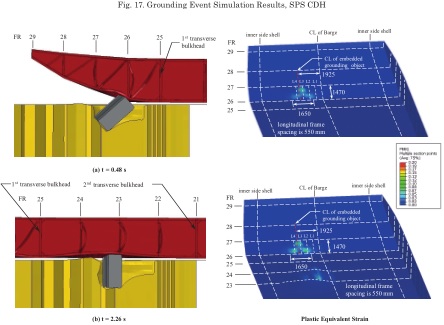
Fig. 17 illustrates the extent of damage to the SPS CDH which is significantly less than for the double hull construction. The damage is spread over a larger width as the load is distributed and there is no growth in the damaged area. The embedded object is struck and the barge is deflected upwards and rides over top of the embedded object and continues to move forward. The maximum energy absorbed is similar to that for the double hull construction. It is anticipated that the barge convoy would come to rest after damage to the 3rd barge based on the results from the graphical energy plots. The results demonstrate that rupture is prevented for the specified grounding event and therefore there is no oil outflow and no oil pollution. The SPS CDH construction demonstrates that it must be equivalent or better than a double bottom construction for protection against oil pollution.
Part 7 of the ABS Rules for Building and Classing Steel Vessels for Service on Rivers and Intracoastal Waterways[1] state that for inspections after construction of the vessel, the ABS Rules for Survey After Construction (Part 7) is to be referenced. Some of the relevant clauses within these rules regarding inspection are given below.
“Side and bottom plating externally. The shell plating is to be examined for excessive corrosion, or deterioration due to chafing or contact with the ground and for any undue unfairness or buckling. Plate unfairness or other deterioration which does not necessitate immediate repairs is to be recorded.”
The SPS CDH construction allows these inspection processes to be completed efficiently within a safe and easily accessible environment.
The key difference between double hull construction and SPS CDH for inspection and maintenance is that void spaces exist in both the double bottom and wing tanks for the double hull construction and are restricted to the wing tanks only for SPS CDH construction. The wing tank structure is common to both. As part of the inspection process, the thickness measurements are to be made on plating from within the cargo tank and possibly to the outer hull plating from outside depending upon where corrosion is more likely to occur. The double bottom construction has the following negative impacts associated with the void space created by the double bottom construction:
The SPS CDH construction mitigates the negative consequences associated with corrosion, inspection and maintenance in the 610 mm void space of the double bottom construction as there is no void space between the inner and outer skin of the hull structure.
The steel faceplates and polyurethane core used in SPS CDH are 100% recyclable. The components are separated. The steel is recycled normally and the polyurethane core is broken down into small pieces using an industrial waste shredder and reused as rubble core (similar to aggregate) in new composite sandwich plates.
For conventional double bottom construction, the responsibility for damage stability verification is placed on the designer of the vessel. Although Part 3, Chapter 2, Section 1, Clause 19.1.1 of the ABS Rules for Building and Classing Steel Vessels for Service on Rivers and Intracoastal Waterways[1], as stated below, refers to stability when tanks are being filled or emptied, it is assumed that it is equally applicable to the stability when damage occurs that may cause flooding of the double bottom/wing tanks.
“It is assumed that those responsible for the design of the vessels have assured themselves that the subdivision is such as to ensure sufficient stability in service when the tanks are being filled or emptied.”
For SPS CDH construction, since it was demonstrated that there is no rupture and no oil outflow for a specified grounding event, there will be no flooding of the cargo space and therefore a damage stability assessment is not required.
The SPS CDH design provides a double bottom structure that is equivalent to or better than double hull construction in protecting the environment against oil outflow and oil pollution and provides significant economic benefits which are described in this section. It is simple and fast to construct and requires no changes to cargo handling systems or inspection and maintenance cycles. SPS CDH is approximately 2.0% lighter than the double hull construction and allows 1% more volume of cargo to be transported. The key commercial drivers that impact the costs and time associated with using SPS CDH for the barge conversion include the following: (a) reduced installation costs; (b) reduced installation time; (c) increased revenue opportunity; and; (d) reduced inspection/ maintenance cycles. These items are discussed below and were determined from a study of a typical fleet of inland waterway barges.
The SPS CDH design provides a 15% overall cost saving compared to double bottom construction for a typical barge fleet with added cost advantage accrued over the life of the barges.
MARPOL regulations stipulate that all single hull oil carrying barges, designed to meet ABS Rules for Building and Classing Steel Vessels for Service on Rivers & Intracoastal Waterways[1], must be made of double skin construction or modified by an alternate construction provided that the construction ensures an equivalent level of protection against oil pollution. The conventional solution consists of adding a double hull structure to the cargo tank region of a single hull barge in accordance with ABS Rules. However, the rules do not provide a structure which is consistent with a specified grounding event. The specified grounding event is based on rupture and not on energy absorption where a small amount of energy is absorbed relative to the input (kinetic) energy. Furthermore, although the double hull construction meets the MARPOL regulations, the greatest protection is not provided where the initial impact is anticipated (transition area in the bow section).
A grounding simulation study for single hull barge construction was conducted to: ensure the simulation of grounding events is a reasonable representation of the actual conditions; verify the soil characteristics and behaviour; evaluate the effect of different embedded objects. The study was based on a barge convoy consisting of 8 tank barges and a push tug with a total mass of 10,514 tonnes and traveling with a maximum velocity of 16 km/hr. The navigable channel is dredged regularly and therefore the conditions of the river bed are well known. The embedded objects used consisted of a rock with a diameter of 100 mm, as determined from dredging operations, up to a maximum rock size with a diameter of 1200 mm (1728 times the mass of the 100 mm diameter rock). The mechanism of grounding events is extremely complex and there are no papers or few records of grounding reports that can be used to expand the knowledge base and confirm the modeling approach. In an effort to simplify the problem and simulate the grounding events, a number of modeling assumptions were made.
Based on the experience gained from conducting a grounding simulation study for single hull barge construction, a comparative grounding simulation study for the double hull construction and SPS CDH construction was completed. The double hull barge was subjected to a specified grounding event which causes rupture of both the inner and outer hull of the double bottom construction to occur resulting in oil outflow and oil pollution. The SPS CDH was designed such that after the initial contact from the specified grounding event was absorbed, the barge rides over top of the embedded object with no rupture, no oil outflow and no oil pollution therefore not only satisfying but exceeding the criterion as stipulated in MEPC.110 (49)[4]. If the grounding event is not severe, it is possible that the damage may be such that repair is not required and that the barge may be subject to and resist future grounding events.
The challenges associated with inspection and maintenance procedures required for double hull construction, where void spaces exist in both the double bottom and wing tanks, are advantageously mitigated for SPS CDH construction. The SPS CDH construction allows inspection and maintenance procedures to be conducted with less risk and more efficiently within a safe and easily accessible environment.
Damage stability verification is required for double hull construction as flooding may occur in the double bottom/wing tanks. For SPS CDH construction, since it was demonstrated that there is no rupture and no oil outflow for a specified grounding event, there will be no flooding of the cargo space and therefore a damage stability assessment is not required.
A detailed assessment of a typical barge fleet indicates that there is a 15% cost saving with added cost advantage accrued over the life of the barges.
IE has demonstrated that the SPS CDH alternative design provides a bottom hull structure that is equivalent to or better than double hull construction in protecting the environment against oil outflow and oil pollution due to a grounding event.
[1] AMERICAN BUREAU OF SHIPPING, 2016, ABS Rules for Building and Classing Steel Vessels for Service on Rivers & Intracoastal Waterways, American Bureau of Shipping, Houston, TX, USA.
[2] INTELLIGENT ENGINEERING, 2016, Equivalent SPS Compact Double Hull (CDH) Bottom Structure for Grounding of Inland Waterway Barges, Intelligent Engineering, Ottawa, Ontario, Canada.
[3] INTERNATIONAL MARITIME ORGANIZATION, 1973, International Convention for the Prevention of Pollution from Ships (MARPOL), International Maritime Organization, London, United Kingdom.
[4] INTERNATIONAL MARITIME ORGANIZATION, 2003, Revised Interim Guidelines for the Approval of Alternative Methods of Design and Construction of Oil Tankers under Regulation 13F(5) of Annex I of MARPOL 73/78”, Resolution MEPC.110 (49), International Maritime Organization, London, United Kingdom.
[5] PICHLER, T. et al., 2012, High-Performance Abaqus Simulations in Soil Mechanics Reloaded — Chances and Frontiers, 2012 Simulia Community Conference, Providence, RI, USA.
[6] SIMULIA, 2016, ABAQUS/CAE 2016 Documentation, Dassault Systemes Simulia Corp., Providence, RI, USA.
[7] SUBRAMANIAN N., 2016, Design of Steel Structures, Oxford University Press, New Delhi, India.
[8] UNITED STATES COAST GUARD, 1994, Navigation and Vessel Inspection Circular No. 15-91, United States Department of Transportation, United States Coast Guard, Washington D.C., USA.